Quicklinks
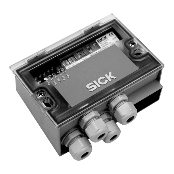
C D B 4 2 0
A n s c h l u s s m o d u l f ü r B a rc o d e s c a n n e r
C LV 4 2 x . . . 4 5 x , I C R 8 4 x / 8 5 x ,
CLV480 und CLV/X490
B e t r i e b s a n l e i t u n g
1. Produkteigenschaften
■
Kleines Anschlussmodul zum Anschluss eines C LV 42x ... 45x,
ICR8 4x /85x, CLV480 oder C LV /X 4 9 0 an Host, CAN-Scanner-
Netzwerk, Peripherie und Stromversorgung
■
Basis zur Aufnahme eines CMC400 (Connection Module Cloning)
für externe Speicherung der Scanner-Parameter
■
9-pol. D-Sub-Stecker intern, für Anschluss der Aux-Schnittstelle
(RS-232) an PC zur Parametrierung/Diagnose des Scanners
■
Klemmen für Hostschnittstelle, CAN-Bus (CDB420-101: 2 x M12-
Steckverbindungen), Schaltein- und -ausgänge, Stromversorgung
■
Von außen sichtbar: LEDs zur Anzeige von aktiven Schaltein- und
ausgängen sowie Schalterstellungen der Modulkonfiguration
■
Schutzart IP 65
■
Montierbar bei geschlossenem Deckel
■
Wartungsfrei
■
UL-zertifiziert bei Verwendung eines Class 2-Netzgeräts
(geprüft nach UL 1310) zur Stromversorgung
Weitere Produktinformationen, Programm „CLV-Connect":
Siehe „www.sick.com/cdb"
EG-Konformitätserklärung:
Auf Anforderung
2. Voraussetzungen zur Installation und Inbetriebnahme
■
Anschlusspläne in CLV-Connect (auf CD „Manuals & Software Bar
Code Scanners", die dem Scanner beiliegt, oder via Internet)
■
Versorgungsspannung DC 24 V, erzeugt nach IEC 742
3. Montage
■
Stets freier Zugang zum internen Stecker „AUX" erforderlich für
Zugriff auf Scanner (Parametrierung/Diagnose)
■
Maximale Leitungslänge zwischen CDB420 und Scanner beim
Einsatz von Verlängerungsleitungen: 10 m (RS-232-Schnittstelle!)
■
Abgenommener Deckel mit Anschlussbild um 180° gedreht in
Parkposition arretierbar
Bohrungs- und Gehäusemaße siehe Maßbild (Seite 4), max.
Schraubendurchmesser 4 mm.
Einbau und Inbetriebnahme des optionalen CMC400 siehe
Betriebsanleitung „CMC400" (Nr. 8010002).
8010001/01-2006
Bar
Code
Scanner
Licht-
schranke
(Lesetakt)
Photo reflex
"Sensor 1"
switch
(Reading clock)
"Sensor 2"
Schalter/switch
Teach-in matchcode
C o n n e c t i o n M o d u l e f o r
CLV42x to 45x, ICR84x/85x, CLV480
a n d C LV / X 4 9 0 B a r C o d e S c a n n e r
O p e r a t i n g I n s t r u c t i o n s
1. Features
■
Compact connection module for connecting a C LV 42x to 4 5 x ,
I C R 8 5 x, CLV480, or C LV/X 4 9 0 to the host, CAN scanner
network, peripheral equipment, and power supply
■
Basis for CMC400 (Connection Module Cloning) integration for
external storage of the scanner parameters
■
9-pin internal D-Sub connector, for connecting the Aux interface
(RS 232) to a PC for configuring/troubleshooting the scanner
■
Terminals for host interface, CAN bus (CDB420-101: 2 x M12
connectors), switching inputs/outputs, and power supply
■
Externally visible LEDs for displaying active switching inputs and
outputs, as well as switch settings for module configuration
■
Enclosure rating IP 65
■
Installation possible with closed cover
■
Maintenance-free
■
UL certificated when a class 2 power supply according to
UL 1310 is used
Further Product Information, "CLV-Connect" PC Program:
See "www.sick.com/cdb"
EC Conformity Declaration:
On request
2. Installation and Commissioning Requirements
■
Connection diagrams in CLV-Connect (on the "Manuals &
Software Bar Code Scanners" CD, provided with the scanner or
from the Internet)
■
24 V DC power supply generated in accordance with IEC 742
3. Installation
■
Permanent access to internal "AUX" connector is required for
access to scanner (configuration/troubleshooting)
■
Maximum cable length between CDB420 and scanner if exten-
sion cables are used: 10 m (32.8 ft) because of RS 232 interf.
■
Cover with connection diagram can be removed, rotated through
180°, and locked in park position
See dimensioned drawing (Page 4) for hole and housing
dimensions, max. screw diameter 4 mm (0.15 in).
For installing and commissioning the optional CMC400, see
"CMC400" Operating Instructions (no. 8010002).
© SICK AG · Division Auto Ident · Germany · All rights reserved
"Aux"
PC
"CAN"
CDB420
CAN Bus
"Host"
HOST
"Result 1"
SPS/PLC
"Result 2"
SPS/PLC
10 ... 30 V DC
1 # 4

Verwandte Anleitungen für SICK CDB420


Inhaltszusammenfassung für SICK CDB420
- Seite 1 Einbau und Inbetriebnahme des optionalen CMC400 siehe For installing and commissioning the optional CMC400, see Betriebsanleitung „CMC400“ (Nr. 8010002). “CMC400” Operating Instructions (no. 8010002). 8010001/01-2006 © SICK AG · Division Auto Ident · Germany · All rights reserved 1 # 4...
- Seite 2 Choose reference potential for switching inputs with switch S 3 parallel mit Stromversorgungs- und Motorleitungen verlegen ■ Bezugspotenzial für die Schalteingänge mit Schalter S 3 wählen 2 # 4 © SICK AG · Division Auto Ident · Germany · All rights reserved 8010001/01-2006...
- Seite 3 2 x 9-pol. D-Sub-Buchse 6027048 CAN BUS data cable, bought to size, twisted pair, shielded 6027048 Datenleitung CAN-BUS, Meterware, twisted pair, geschirmt 8010001/01-2006 © SICK AG · Division Auto Ident · Germany · All rights reserved 3 # 4...
- Seite 4 CAN H CAN bus CAN L Signal (Stecker/plug) Schirm/Shield CAN H CAN bus CAN L Alle Angaben in mm (inch)/All dimensions in mm (inch) 4 # 4 © SICK AG · Division Auto Ident · Germany · All rights reserved 8010001/01-2006...