Lenze i500 Montage- Und Einschaltanleitung
Vorschau ausblenden
Andere Handbücher für i500:
- Montage- und einschaltanleitung (76 Seiten) ,
- Montageanleitung (20 Seiten) ,
- Montageanleitung (12 Seiten)

Verwandte Anleitungen für Lenze i500


Inhaltszusammenfassung für Lenze i500
- Seite 1 0.25 ... 2.2 kW Montage- und Einschaltanleitung Inverter i510-Cabinet Mounting and switch-on instructions...
- Seite 2 Diese Seite wurde absichtlich leer gelassen.
-
Seite 3: Inhaltsverzeichnis
Inhalt Inhalt 1 Allgemeines 1.1 Erst lesen, dann beginnen 1.2 Schreibweisen und Konventionen 1.2.1 Produktcode 2 Sicherheitshinweise 2.1 Grundlegende Sicherheitsmaßnahmen 2.2 Restgefahren 2.3 Bestimmungsgemäße Verwendung 3 Produktbeschreibung 4 Montage 4.1 Wichtige Hinweise 4.2 Mechanische Installation 4.3 Elektrische Installation 4.3.1 Anschluss an das 230 V-Netz 4.3.1.1 Anschlussplan 4.3.1.2... -
Seite 4: Allgemeines
Erst lesen, dann beginnen WARNUNG! Lesen Sie vor der Installation und Inbetriebnahme sorgfältig diese Dokumentation. ▶ Beachten Sie die Sicherheitshinweise! Informationen und Hilfsmittel rund um die Lenze-Produkte finden Sie im Internet: http://www.lenze.com à Download Schreibweisen und Konventionen 1.2.1 Produktcode In Tabellen werden die ersten 9 Stellen des jeweiligen Produktcodes verwendet, um die Produkte zu identifi‐... -
Seite 5: Sicherheitshinweise
Sicherheitshinweise Grundlegende Sicherheitsmaßnahmen Sicherheitshinweise Grundlegende Sicherheitsmaßnahmen Wenn Sie die folgenden grundlegenden Sicherheitsmaßnahmen missachten, kann dies zu schweren Perso- nenschäden und Sachschäden führen! Das Produkt • ausschließlich bestimmungsgemäß verwenden. • niemals trotz erkennbarer Schäden in Betrieb nehmen. • niemals technisch verändern. •... -
Seite 6: Restgefahren
Sicherheitshinweise Restgefahren Restgefahren Die genannten Restgefahren muss der Anwender in der Risikobeurteilung für seine Maschine/Anlage berücksichtigen. Nichtbeachtung kann zu schweren Personenschäden und Sachschäden führen! Produkt Beachten Sie die Warnschilder auf dem Produkt! Symbol Beschreibung Elektrostatisch gefährdete Bauelemente: Vor Arbeiten am Inverter muss sich das Personal von elektrostatischen Aufladungen befreien! Gefährliche elektrische Spannung: Vor Arbeiten am Inverter überprüfen, ob alle Leistungsanschlüsse spannungslos sind! Die Leistungsanschlüsse X100 und X105 führen nach Netz-Ausschalten für die auf dem Inverter angegebene Zeit gefährliche elektrische... -
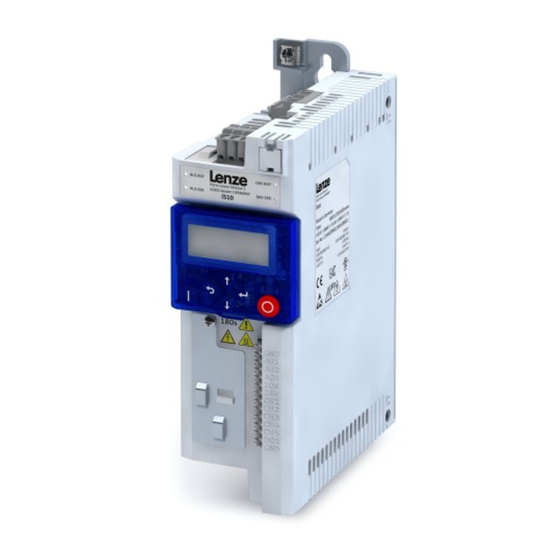
Seite 7: Produktbeschreibung
Produktbeschreibung Produktbeschreibung PE-Anschluss Netzanschluss X100 Relaisausgang X9 IT-Schraube Netzwerk X216 CANopen/Modbus (Op on) Speichermodul X20 Status-LEDs Netzwerk Status-LEDs Inverter Schirmauflage CANopen/Modbus Umschalter CANopen/Modbus Schni stelle X16 Diagnosemodul Steuerklemmen X3 Basis I/O Schirmauflage IT-Schraube Steueranschlüsse Motoranschluss X105... -
Seite 8: Montage
Montage Wichtige Hinweise Montage Wichtige Hinweise GEFAHR! Gefährliche elektrische Spannung Mögliche Folge: Tod oder schwere Verletzungen ▶ Alle Arbeiten am Inverter nur im spannungslosen Zustand durchführen. ▶ Nach dem Abschalten der Netzspannung mindestens 3 Minuten warten, bevor Sie mit den Arbeiten beginnen. -
Seite 9: Mechanische Installation
Montage Mechanische Installation Mechanische Installation Abmessungen i51AE 0,25 kW ... 0,37 kW Alle Maße in mm... - Seite 10 Montage Mechanische Installation Abmessungen i51AE 0,55 kW ... 0,75 kW Alle Maße in mm...
- Seite 11 Montage Mechanische Installation Abmessungen i51AE 1,1 kW ... 2,2 kW Alle Maße in mm...
-
Seite 12: Elektrische Installation
Montage Elektrische Installation Anschluss an das 230 V-Netz Elektrische Installation 4.3.1 Anschluss an das 230 V-Netz 4.3.1.1 Anschlussplan 3/N/PE AC 400 V 1/N/PE AC 230 V Modbus CANopen AC 240 V, 3 A Basic I/O +24 V +10 V 100 mA "... -
Seite 13: Sicherungen Und Leitungsquerschnitte
Montage Elektrische Installation Anschluss an das 230 V-Netz 4.3.1.2 Sicherungen und Leitungsquerschnitte Betrieb ohne Netzdrossel Leitungsinstallation nach EN 60204-1 Verlegeart B2 Inverter I51AE125B I51AE137B I51AE155B I51AE175B I51AE211B I51AE215B I51AE222B Bemessungsleistung 0.25 0.37 0.55 0.75 Netz-Bemessungsstrom ohne Netzdrossel 14.3 16.7 22.5 Schmelzsicherung Sicherungscharakteristik gG/gL oder gRL... -
Seite 14: Klemmendaten
Montage Elektrische Installation Anschluss an das 230 V-Netz 4.3.1.3 Klemmendaten Netzanschluss Inverter I51AE125B I51AE137B I51AE155B I51AE175B I51AE211B I51AE215B I51AE222B Bemessungsleistung 0.25 0.37 0.55 0.75 Anschluss X100 Anschlusstyp Schraubklemme Min. Leitungsquerschnitt mm² Max. Leitungsquerschnitt mm² Abisolierlänge Anziehdrehmoment Benötigtes Werkzeug 0.5 x 3.0 0.6 x 3.5 Motoranschluss Inverter... -
Seite 15: Anschluss An Das 400 V-Netz
Montage Elektrische Installation Anschluss an das 400 V-Netz 4.3.2 Anschluss an das 400 V-Netz 4.3.2.1 Anschlussplan 3/N/PE AC 400 V … 3/PE AC 400 V Modbus CANopen AC 240 V, 3 A Basic I/O +24 V +10 V 100 mA "... -
Seite 16: Sicherungen Und Leitungsquerschnitte
Montage Elektrische Installation Anschluss an das 400 V-Netz 4.3.2.2 Sicherungen und Leitungsquerschnitte Betrieb ohne Netzdrossel Leitungsinstallation nach EN 60204-1 Verlegeart B2 Inverter I51AE137F I51AE155F I51AE175F I51AE211F I51AE215F I51AE222F Bemessungsleistung 0.37 0.55 0.75 Netz-Bemessungsstrom ohne Netzdrossel Schmelzsicherung Sicherungscharakteristik gG/gL oder gRL Max. -
Seite 17: Klemmendaten
Montage Elektrische Installation Anschluss an das 400 V-Netz 4.3.2.3 Klemmendaten Netzanschluss Inverter I51AE137F I51AE155F I51AE175F I51AE211F I51AE215F I51AE222F Bemessungsleistung 0.37 0.55 0.75 Anschluss X100 Anschlusstyp Schraubklemme Min. Leitungsquerschnitt mm² Max. Leitungsquerschnitt mm² Abisolierlänge Anziehdrehmoment Benötigtes Werkzeug 0.5 x 3.0 Motoranschluss Inverter I51AE137F I51AE155F... -
Seite 18: Anschluss An Das It-Netz
Montage Elektrische Installation Anschluss an das IT-Netz 4.3.3 Anschluss an das IT-Netz ACHTUNG! Interne Bauteile haben Erdpotenzial, wenn die IT-Schrauben nicht entfernt werden. Folge: Die Überwachungseinrichtungen des IT-Netzes sprechen an. ▶ Vor dem Anschluss an ein IT-Netz unbedingt die IT-Schrauben entfernen. I51AE125B, I51AE137B I51AE155B, I51AE175B, I51AE211B, I51AE215B, I51AE222B I51AE137F... -
Seite 19: Anschluss Canopen/Modbus
Montage Elektrische Installation Anschluss CANopen/Modbus 4.3.4 Anschluss CANopen/Modbus 4.3.4.1 Anschlussplan X216 X216 X216 X216 Abb. 3: Anschlussbeispiel: CANopen oder Modbus-Netzwerk 4.3.4.2 Klemmendaten Beschreibung des CANopen/Modbus Anschlusses Anschluss X216 Anschlusstyp Federkraftklemme Min. Leitungsquerschnitt mm² Max. Leitungsquerschnitt mm² Abisolierlänge Anziehdrehmoment Benötigtes Werkzeug 0.4 x 2.5 4.3.4.3 Netzwerk-Grundeinstellungen Das Netzwerk muss am physikalisch ersten und letzten Busteilnehmer mit einem 120 Ω-Widerstand... -
Seite 20: Inbetriebnahme
Inbetriebnahme Wichtige Hinweise Inbetriebnahme Wichtige Hinweise WARNUNG! Fehlerhafte Einstellungen während der Inbetriebnahme können unerwartete und gefährliche Motor− und Anlagenbewegungen auslösen. Mögliche Folge: Tod, schwere Verletzungen oder Sachschäden ▶ Gefahrenbereich räumen. ▶ Sicherheitsvorschriften und Sicherheitsabstände einhalten. Vor dem ersten Einschalten Verhindern Sie Personenschäden und Sachschäden. Prüfen Sie vor dem Einschalten der Netzspannung: •... -
Seite 21: Erstes Einschalten / Funktionstest Mit Klemmensteuerung
Zielsetzung: Den am Inverter angeschlossenen Motor innerhalb kürzester Zeit zum Drehen bringen. Voraussetzungen: • Der angeschlossene Motor passt leistungsmäßig zum Inverter. • Die Parametereinstellungen entsprechen dem Auslieferungszustand (Lenze-Einstellung). 1. Vorbereitung: 1. Die Leistungsanschlüsse verdrahten. (Kapitel 4.3 Elektrische Installation) 2. Die Digitaleingänge X3/DI1 (Start/Stop), X3/DI3 (Drehrichtungsumkehr) und X3/DI4 (Frequenz-Preset 20 Hz) verdrahten. - Seite 22 1. Frequenz-Preset 1 wieder deaktivieren: X3/DI4 = LOW. 2. Inverter wieder stoppen: X3/DI1 = LOW. Der Funktionstest ist abgeschlossen. Die Inbetriebnahme der Antriebslösung ist in einer separaten Inbetriebnahmeanleitung beschrie- ben. Diese finden Sie im Internet in unserem Downloadbereich: http://www.lenze.com à Download...
-
Seite 23: Technische Daten
Technische Daten Normen und Einsatzbedingungen Technische Daten Normen und Einsatzbedingungen Konformitäten 2014/35/EU Niederspannungsrichtlinie 2014/30/EU EMV-Richtlinie (Bezug: CE-typisches Antriebssystem) TR TC 004/2011 Eurasische Konformität: Sicherheit von Niederspannungsausrüstung TP TC 020/2011 Eurasische Konformität: Elektromagnetische Verträglichkeit von technischen Erzeugnissen RoHS 2 2011/65/EU Beschränkung der Verwendung bestimmter gefährlicher Stoffe in Elektro- und Elektronikgeräten Approbationen UL 61800-5-1... - Seite 24 Technische Daten Normen und Einsatzbedingungen Netzstrom > 16 A: Mit Netzdrossel EN 61000-3-12 Rsce: Kurzschlussleistungsverhältnis am oder Netzfilter, bei Auslegung für Anschlusspunkt der Maschine/Anlage zum Bemessungsleistung. Rsce ≥ 120 ist öffentlichen Netz zu erfüllen. Anforderungen an die geschirmte Motorleitung Kapazitätsbelag C-Ader-Ader/C-Ader-Schirm <...
-
Seite 25: Bemessungsdaten
Technische Daten Bemessungsdaten Anschluss an das 230 V-Netz Bemessungsdaten 6.2.1 Anschluss an das 230 V-Netz Inverter I51AE125B I51AE137B I51AE155B I51AE175B I51AE211B I51AE215B I51AE222B Bemessungsleistung 0.25 0.37 0.55 0.75 Netzspannungsbereich 1/N/PE AC 170 V ... 264 V, 45 Hz ... 55 Hz Betriebsart Max. - Seite 26 This page intentionally left blank!
- Seite 27 Contents Contents 1 General information 1.1 First read, then start 1.2 Notations and conventions 1.2.1 Product code 2 Safety instructions 2.1 Basic safety measures 2.2 Residual hazards 2.3 Application as directed 3 Product description 4 Mounting 4.1 Important notes 4.2 Mechanical installation 4.3 Electrical installation 4.3.1 Connection to the 230 V system...
-
Seite 28: General Information
WARNING! Read this documentation thoroughly before carrying out the installation and commissioning. ▶ Please observe the safety instructions! Information and tools with regard to the Lenze products can be found on the Internet: http://www.lenze.com à Download Notations and conventions 1.2.1... -
Seite 29: Safety Instructions
The procedural notes and circuit details described in this document are only proposals. It is up to the user to check whether they can be adapted to the particular applications. Lenze does not take any responsibility for the suitability of the procedures and circuit proposals described. -
Seite 30: Residual Hazards
Safety instructions Residual hazards Residual hazards The user must take the residual hazards mentioned into consideration in the risk assessment for his/her machine/system. If the above is disregarded, this can lead to severe injuries to persons and damage to material assets! Product Observe the warning labels on the product! Icon... -
Seite 31: Product Description
Product description Product description Earth / ground connec on (PE) Mains voltage connec on X100 Relay output X9 IT screw from 0.55 kW Network X2xx CANopen/Modbus (Op on) Memory module X20 Network status-LEDs Inverter status LEDs Shield connec on CANopen/Modbus Toggle switch CANopen/Modbus Interface X16... - Seite 32 Mounting Important notes Mounting Important notes DANGER! Dangerous electrical voltage Possible consequence: death or severe injuries ▶ All works on the inverter must only be carried out in the deenergised state. ▶ After switching off the mains voltage, wait for at least 3 minutes before you start working.
-
Seite 33: Mounting
Mounting Mechanical installation Mechanical installation Dimensions I51AE 0.25 kW ... 0.37 kW All dimensions in mm... - Seite 34 Mounting Mechanical installation Dimensions I51AE 0.55 kW ... 0.75 kW All dimensions in mm...
- Seite 35 Mounting Mechanical installation Dimensions I51AE 1.1 kW ... 2.2 kW All dimensions in mm...
-
Seite 36: Electrical Installation
Mounting Electrical installation Connection to the 230 V system Electrical installation 4.3.1 Connection to the 230 V system 4.3.1.1 Connection plan 3/N/PE AC 400 V 1/N/PE AC 230 V Modbus CANopen AC 240 V, 3 A Basic I/O +24 V +10 V 100 mA "... -
Seite 37: Fuses And Cable Cross-Sections
Mounting Electrical installation Connection to the 230 V system 4.3.1.2 Fuses and cable cross-sections Operation without mains choke Cable installation in compliance with EN 60204-1 Laying system B2 Inverter I51AE125B I51AE137B I51AE155B I51AE175B I51AE211B I51AE215B I51AE222B Rated power 0.25 0.37 0.55 0.75 Rated mains current... -
Seite 38: Terminal Data
Mounting Electrical installation Connection to the 230 V system 4.3.1.3 Terminal data Mains connection Inverter I51AE125B I51AE137B I51AE155B I51AE175B I51AE211B I51AE215B I51AE222B Rated power 0.25 0.37 0.55 0.75 Connection X100 Connection type Screw terminal Min. cable cross-section mm² Max. cable cross-section mm²... -
Seite 39: Connection Plan
Mounting Electrical installation Connection to the 400 V system 4.3.2 Connection to the 400 V system 4.3.2.1 Connection plan 3/N/PE AC 400 V … 3/PE AC 400 V Modbus CANopen AC 240 V, 3 A Basic I/O +24 V +10 V 100 mA "... -
Seite 40: Fuses And Cable Cross-Sections
Mounting Electrical installation Connection to the 400 V system 4.3.2.2 Fuses and cable cross-sections Operation without mains choke Cable installation in compliance with EN 60204-1 Laying system B2 Inverter I51AE137F I51AE155F I51AE175F I51AE211F I51AE215F I51AE222F Rated power 0.37 0.55 0.75 Rated mains current without mains choke Fuse... -
Seite 41: Terminal Data
Mounting Electrical installation Connection to the 400 V system 4.3.2.3 Terminal data Mains connection Inverter I51AE137F I51AE155F I51AE175F I51AE211F I51AE215F I51AE222F Rated power 0.37 0.55 0.75 Connection X100 Connection type Screw terminal Min. cable cross-section mm² Max. cable cross-section mm² Stripping length Tightening torque Required tool... -
Seite 42: Connection To The It System
Mounting Electrical installation Connection to the IT system 4.3.3 Connection to the IT system NOTICE! Internal components have earth/ground potential if the IT screws are not removed. Consequence: the monitoring functions of the IT system respond. ▶ Before connection to an IT system be absolutely sure to remove the IT screws. I51AE125B, I51AE137B I51AE155B, I51AE175B, I51AE211B, I51AE215B, I51AE222B I51AE137F... -
Seite 43: Canopen/Modbus Connection
Mounting Electrical installation CANopen/Modbus connection 4.3.4 CANopen/Modbus connection 4.3.4.1 Connection plan X216 X216 X216 X216 Fig. 3: Wiring example: CANopen or Modbus network 4.3.4.2 Terminal data Terminal description CANopen/Modbus Connection X216 Connection type Spring terminal Min. cable cross-section mm² Max. cable cross-section mm²... -
Seite 44: Commissioning
Commissioning Important notes Commissioning Important notes WARNING! Incorrect settings during commissioning may cause unexpected and dangerous motor and system movements. Possible consequence: death, severe injuries or damage to property ▶ Clear hazardous area. ▶ Observe safety instructions and safety clearances. Before initial switch-on Prevent injury to persons and damage to property. -
Seite 45: Initial Switch-On / Functional Test With Terminal Control
Target: achieve rotation of the motor connected to the inverter as quickly as possible. Requirements: • The connected motor matches the inverter in terms of power. • The parameter settings comply with the delivery status (Lenze setting). 1. Preparation: 1. Wiring of power terminals. (Chapter 4.3 Electrical installation) 2. - Seite 46 2. Stop inverter again: X3/DI1 = LOW. The functional test is completed. The commissioning process of the drive solution is described in a separate commissioning instruc- tion which can be found on the Internet in our download area: http://www.lenze.com à Download...
-
Seite 47: Technical Data
Technical data Standards and operating conditions Technical data Standards and operating conditions Conformities 2014/35/EU Low-Voltage Directive 2014/30/EU EMC Directive (reference: CE-typical drive system) TR TC 004/2011 Eurasian conformity: Safety of low voltage equipment TP TC 020/2011 Eurasian conformity: Electromagnetic compatibility of technical means RoHS 2 2011/65/EU... - Seite 48 Technical data Standards and operating conditions dimensioning for rated power. Rsce ≥ 120 is to be met. Requirements to the shielded motor cable Capacitance per unit length C-core-core/C-core-shield < 75/150 ≤ 2,5 mm² / AWG 14 pF/m C-core-core/C-core-shield < 150/300 ≥...
-
Seite 49: Rated Data
Technical data Rated data Connection to the 230 V system Rated data 6.2.1 Connection to the 230 V system Inverter I51AE125B I51AE137B I51AE155B I51AE175B I51AE211B I51AE215B I51AE222B Rated power 0.25 0.37 0.55 0.75 Mains voltage range 1/N/PE AC 170 V ... 264 V, 45 Hz ... 55 Hz Operating mode Max. - Seite 52 © 09/2015 | 13492595 | 1.0 Lenze Drives GmbH Ö Postfach 10 13 52, D-31763 Hameln Breslauer Straße 3, D-32699 Extertal Germany HR Lemgo B 6478 +49 5154 82-0 Ü +49 5154 82-2800 Ø [email protected] Ù www.lenze.com Ú Lenze Service GmbH Û...