HYDAC ELECTRONIC HFS 2100 Bedienungsanleitung
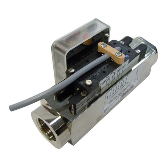
Elektromechanischer durchfluss-schalter mit atex-zulassung für öle / viskose medien
Vorschau ausblenden
Andere Handbücher für HFS 2100:
- Bedienungsanleitung (32 Seiten) ,
- Bedienungsanleitung (52 Seiten)
Inhaltsverzeichnis
Verfügbare Sprachen
Verfügbare Sprachen
Quicklinks
Elektromechanischer Durchfluss-Schalter
HFS 2100 mit ATEX-Zulassung
Electro-Mechanical Flow Switch HFS 2100
Schutzklassen und Einsatzbereiche:
Protection ratings and applications:
Bescheinigungsnummer:
Certificate:
Prüfstelle:
Certified body:
Status 19.05.2020
Bedienungsanleitung
für Öle / Viskose Medien
(Original-Bedienungsanleitung)
Operating Instructions
with ATEX approval
for oil / viscous media
(Translation of the original operating instructions )
HYDAC ELECTRONIC GMBH
II 2G Ex mb IIC T5, T6 Gb
II 2D Ex tb IIIC T80 °C, T100 °C Db
PTB 19 ATEX 2008 X
Physikalisch-Technische
Bundesanstalt Braunschweig
Mat.No.: 669863
Inhaltsverzeichnis

Verwandte Anleitungen für HYDAC ELECTRONIC HFS 2100


Inhaltszusammenfassung für HYDAC ELECTRONIC HFS 2100
- Seite 1 Elektromechanischer Durchfluss-Schalter HFS 2100 mit ATEX-Zulassung für Öle / Viskose Medien (Original-Bedienungsanleitung) Operating Instructions Electro-Mechanical Flow Switch HFS 2100 with ATEX approval for oil / viscous media (Translation of the original operating instructions ) Schutzklassen und Einsatzbereiche: II 2G Ex mb IIC T5, T6 Gb Protection ratings and applications: II 2D Ex tb IIIC T80 °C, T100 °C Db...
-
Seite 2: Inhaltsverzeichnis
Durchfluss-Schalter HFS 2100 ATEX Seite 2 Inhaltsverzeichnis Allgemeines ..........................3 Funktion ........................... 3 Sicherheitshinweise ........................3 Allgemeine Hinweise ......................3 Bestimmungsgemäße Verwendung ................... 4 Qualifiziertes Personal ....................... 4 Warnhinweise ........................4 Montage ........................... 5 Prozessanschluss ......................5 Mechanische Installation ....................5 Umgebungsbedingungen .................... -
Seite 3: Allgemeines
Falls Sie Fragen bezüglich der technischen Daten oder Eignung für Ihre Anwendungen haben, wenden Sie sich bitte an unseren technischen Vertrieb. Die Durchfluss-Schalter der Serie HFS 2100 zeichnen sich durch zuverlässige Funktion und einfache Bedienung aus. Sie sind wartungsfrei und sollten beim Einsatz innerhalb der Spezifikationen (siehe Technische Daten) einwandfrei arbeiten. -
Seite 4: Bestimmungsgemäße Verwendung
Störungsfall Personen, Tiere oder Sachen Schaden erleiden können. 3.3 Qualifiziertes Personal Die Geräte der Serie HFS 2100 dürfen nur von qualifiziertem Personal, das in der Lage ist, die Geräte fachgerecht einzusetzen, installiert werden. Qualifiziertes Personal sind Personen, die mit der Aufstellung, Montage, Inbetriebnahme und Betrieb dieser Geräte vertraut sind und die über... -
Seite 5: Montage
Durchfluss-Schalter HFS 2100 ATEX Seite 5 Montage 4.1 Prozessanschluss Achtung! Die folgenden Forderungen müssen unbedingt eingehalten werden, sonst werden Durchfluss-Schalter oder Anlage beschädigt: - Bauseitig muss ein zum Gerät passender Prozessanschluss vorhanden sein - Anschlussgröße überprüfen - Einschraubtiefe überprüfen - Geeignete Dichtmittel verwenden (flüssige Dichtmittel beschädigen den Durchfluss-... -
Seite 6: Elektrische Installation
Betriebsmittel und unter Beachtung der Bestimmungen zur Errichtung von elektrischen Betriebsmitteln in explosionsgefährdeten Bereichen zu erfolgen. Die Durchfluss-Schalter der Serie HFS 2100 tragen das - Zeichen nach Richtlinie 2014/34/EU. Die Anschlussstromkreise sind in erhöhter Sicherheit auszuführen, sofern das Gerät nicht an eigensichere Stromkreise angeschlossen wird. -
Seite 7: Besondere Bedingungen
Durchfluss-Schalter HFS 2100 ATEX Seite 7 Der Stromkreis darf weder wirksame Induktivitäten noch wirksame Kapazitäten enthalten. Oben genannte Grenzwerte dürfen zu keiner Zeit überschritten werden. Zum Schutz des Schaltkontakts ist außerhalb des explosionsgefährdeten Bereiches eine Sicherung mit einem Nennwert von: 1 A für Wechsler-Kontakt SEM-A... -
Seite 8: Elektrischer Anschluss
Durchfluss-Schalter HFS 2100 ATEX Seite 8 4.4.4 Elektrischer Anschluss Die in den Geräten eingesetzten Schaltkontakte sind potentialfrei und benötigen keine Speisung. Achtung! Schaltkontakt und Gerät sind aufeinander abgestimmt. Nach dem Austausch eines Schaltkontaktes muss dieser neu justiert werden. Fordern Sie bitte die entsprechende Montageanleitung an. -
Seite 9: Schaltpunkteinstellung
Durchfluss-Schalter HFS 2100 ATEX Seite 9 Schaltpunkteinstellung - Die Feststellschrauben des Schaltkontakts lösen. - Den Schaltkontakt verschieben, bis der Pfeil auf dem Schaltkontakt mit dem gewünschten Schaltpunkt zur Deckung kommt. - Die Feststellschrauben des Schaltkontakts wieder anziehen. Hinweise: - Der eingestellte Schaltpunkt entspricht dem Abschaltpunkt des Schaltkontakts bei fallendem Durchfluss. -
Seite 10: Technische Daten
Durchfluss-Schalter HFS 2100 ATEX Seite 10 Technische Daten Eingangskenngrößen Schaltbereiche [l/min] Baugröße 1 Baugröße 2 0,5 .. 1,6 0,5 .. 1,5 0,8 .. 3,0 1 .. 2,0 .. 7,0 2 .. 3 .. 10 5 .. 15 8 .. 24 10 .. -
Seite 11: Typenschlüssel Zur Identifikation Des Gelieferten Gerätes
Durchfluss-Schalter HFS 2100 ATEX Seite 11 Typenschlüssel zur Identifikation des gelieferten Gerätes HFS 2 1 X 1 – XX – XXXX–XXXX – 7 – X – X – A00 Messverfahren 2 = Schwebekörper Messmedium 1 = Öle / Viskose Medien Anschlussart mechanisch 1 = 1/4 “... -
Seite 12: Geräteabmessungen
Durchfluss-Schalter HFS 2100 ATEX Seite 12 Geräteabmessungen 9.1 Geräte ohne Anzeige Stand 19.05.2020 Mat.Nr.: 669863 HYDAC ELECTRONIC GMBH... -
Seite 13: Geräte Mit Anzeige
Durchfluss-Schalter HFS 2100 ATEX Seite 13 9.2 Geräte mit Anzeige Stand 19.05.2020 Mat.Nr.: 669863 HYDAC ELECTRONIC GMBH... -
Seite 14: Fehlersuche / Problembehebung
Durchfluss-Schalter HFS 2100 ATEX Seite 14 10 Fehlersuche / Problembehebung 10.1 Der Schaltkontakt schaltet nicht 10.1.1 Der Schaltkontakt ist ständig im Ruhezustand Kein Durchfluss Überprüfen, ob tatsächlich Medium fließt Durchfluss zu gering oder Schaltkontakt zu hoch eingestellt Den Schaltkontakt auf geringen Durchfluss einstellen Ein Gerät mit anderem Schaltbereich verwenden... -
Seite 15: Atex Zertifikat
Durchfluss-Schalter HFS 2100 ATEX Seite 15 11 ATEX Zertifikat Stand 19.05.2020 Mat.Nr.: 669863 HYDAC ELECTRONIC GMBH... - Seite 16 Durchfluss-Schalter HFS 2100 ATEX Seite 16 Stand 19.05.2020 Mat.Nr.: 669863 HYDAC ELECTRONIC GMBH...
- Seite 17 Durchfluss-Schalter HFS 2100 ATEX Seite 17 Stand 19.05.2020 Mat.Nr.: 669863 HYDAC ELECTRONIC GMBH...
-
Seite 18: Konformitätserklärung
Durchfluss-Schalter HFS 2100 ATEX Seite 18 12 Konformitätserklärung Stand 19.05.2020 Mat.Nr.: 669863 HYDAC ELECTRONIC GMBH... - Seite 19 Durchfluss-Schalter HFS 2100 ATEX Seite 19 Stand 19.05.2020 Mat.Nr.: 669863 HYDAC ELECTRONIC GMBH...
- Seite 20 Durchfluss-Schalter HFS 2100 ATEX Seite 20 HYDAC ELECTRONIC GMBH Hauptstr. 27 D-66128 Saarbrücken Germany Web: www.hydac.com E-Mail: [email protected] Tel.: +49 (0)6897 509-01 Fax.: +49 (0)6897 509-1726 HYDAC Service Für Fragen zu Reparaturen steht Ihnen die HYDAC SYSTEMS & SERVICES GMBH zur Verfügung.
- Seite 21 Operating Instructions Electro-Mechanical Flow Switch HFS 2100 with ATEX approval for oil / viscous media (Translation of the original operating instructions ) Protection ratings and applications: II 2G Ex mb IIC T5, T6 Gb II 2D Ex tb IIIC T80 °C, T100 °C Db...
- Seite 22 Flow switch HFS 2100 with ATEX approval Page 2 Content General ............................ 3 Function ........................... 3 Safety information........................3 General hints ........................3 Proper / Designated use..................... 4 Qualified personnel ......................4 Warning notices ......................... 4 Installation ..........................5 Process connection ......................5 Mechanical installation .......................
-
Seite 23: General
Function The instruments type HFS 2100 operate on the principle of the float type flow indicator. Through the flowing medium a float is set in motion, whose integrated magnets create a magnetic field. The position of the float is detected with the switch contact. -
Seite 24: Proper / Designated Use
Page 4 3.2 Proper / Designated use The Flow Switch series HFS 2100 with ATEX approval serve as monitors for continuous flow of liquids in hazardous locations. Any other use counts as non directed. If not indicated otherwise, the scaling of the instruments refer to water. Special applications, where intermittent loads (e.g. cyclic operation) could occur, should be discussed and checked with our technical Staff. -
Seite 25: Installation
Flow switch HFS 2100 with ATEX approval Page 5 Installation 4.1 Process connection Caution! To avoid the damage of the Flow Switch or the installation the following require-ments must be fulfilled under any circumstances: - A suitable process connection has to be provided... -
Seite 26: Electrical Installation
The connection circuits must be designed with increased safety, if the device is not connected to intrinsically safe circuits. The flow switches of the HFS 2100 series carry the - mark in accordance with directive 2014/34/EU. -
Seite 27: Specific Conditions Of Use
Flow switch HFS 2100 with ATEX approval Page 7 The circuit must not incorporate any effective inductivities or effective capacities. For contact protection a fuse with the nominal value of 1 A für Change-over contact SEM-A 2 A für Normally open contact SEM-E must be provided outside of the Hazardous Area for the circuit, unless the switch unit is connected to an intrinsic safe circuit. -
Seite 28: Electrical Connection
Flow switch HFS 2100 with ATEX approval Page 8 4.4.4 Electrical connection The switching contacts used in the instruments are potential free and do not need any supply. Attention! Switching contact and unit are matched. After the exchange of a switching contact a readjustment must be made. -
Seite 29: Switch Point Adjustment
Flow switch HFS 2100 with ATEX approval Page 9 Switch point adjustment - Loosen the lock screw of the switch contact - Shift the switch contact until the arrow on the switch contact is in coincidence with the desired switch point - Tighten the look screw of the switch contact. -
Seite 30: Technical Data
Flow switch HFS 2100 with ATEX approval Page 10 Technical data Input data Switching ranges [l/min] Size 1 Size 2 0.1 .. 0.8 0.5 .. 1.5 0.5 .. 1.6 1 .. 0.8 .. 3.0 2 .. 2.0 .. 7.0 3 .. 10 5 .. -
Seite 31: Model Code To Identify The Delivered Part
Flow switch HFS 2100 with ATEX approval Page 11 Model code to identify the delivered part HFS 2 1 X 1 – XX – XXXX–XXXX – 7 – X – X – A00 Measuring principle 2 = Variable area float... -
Seite 32: Dimensions
Flow switch HFS 2100 with ATEX approval Page 12 Dimensions 9.1 Devices without mechanical indicator Status 2020/05/19 Mat. No.: 669863 HYDAC ELECTRONIC GMBH... -
Seite 33: Devices With Mechanical Indicator
Flow switch HFS 2100 with ATEX approval Page 13 9.2 Devices with mechanical indicator Status 2020/05/19 Mat. No.: 669863 HYDAC ELECTRONIC GMBH... -
Seite 34: Fault Finding Hints
Flow switch HFS 2100 with ATEX approval Page 14 10 Fault finding hints 10.1 The switch contact does not react 10.1.1 The switch contact is permanent in break position No flow Check for medium flow Flow to low or switch contact adjusted to high Adjust switch point to a lower flow... -
Seite 35: Certificate
Flow switch HFS 2100 with ATEX approval Page 15 ertificate Status 2020/05/19 Mat. No.: 669863 HYDAC ELECTRONIC GMBH... - Seite 36 Flow switch HFS 2100 with ATEX approval Page 16 Status 2020/05/19 Mat. No.: 669863 HYDAC ELECTRONIC GMBH...
- Seite 37 Flow switch HFS 2100 with ATEX approval Page 17 Status 2020/05/19 Mat. No.: 669863 HYDAC ELECTRONIC GMBH...
-
Seite 38: Declaration Of Conformity
Flow switch HFS 2100 with ATEX approval Page 18 Declaration of Conformity Status 2020/05/19 Mat. No.: 669863 HYDAC ELECTRONIC GMBH... - Seite 39 Flow switch HFS 2100 with ATEX approval Page 19 Status 2020/05/19 Mat. No.: 669863 HYDAC ELECTRONIC GMBH...
- Seite 40 Flow switch HFS 2100 with ATEX approval Page 20 HYDAC ELECTRONIC GMBH Hauptstr.27 D-66128 Saarbrücken Germany Web: www.hydac.com E-Mail: [email protected] Tel.: +49 (0)6897 509-01 Fax.: +49 (0)6897 509-1726 HYDAC Service For enquiries about repairs, please contact HYDAC SYSTEMS & SERVICES GMBH.